![]()
![]()
![]()
![]()
Installation and Operating Instructions
Solid State Voltage Regulator for Autolite GAS Model Generators (Standard Output)
APPLICATION: This solid state voltage regulator is designed specifically to fit standard output three brush GAS model Autolite generators using a 6 volt negative ground system, positive field winding control and external cutout relay (Standard equipment on all Indian motorcycles from 1930 through 1946).
DO NOT ATTEMPT TO ADAPT THIS REGULATOR TO OTHER APPLICATIONS:
Damage to the generator or regulator may occur
PROPER INSTALLATION WILL REQUIRE THE FOLLOWING:
A properly functioning Autolite model GAS generator configured for Negative Ground Operation Only (See Figure 2 below)
Elimination of the third brush inside the generator, converting it to a two brush system. (See Figure 3 below)
OVERVIEW OF OPERATION: Installation will eliminate the often troublesome three brush regulating system and mechanical cutout relay. It will be replaced with a solid state current and voltage regulator mounted inside an aluminum housing that looks like the original cutout cover. Installed properly, this regulator will allow complete and accurate current and voltage regulation of the generator. Maximum output voltage will be limited to approximately 7.25 volts. Current output will range from approximately .75 amps, up to the maximum allowed by the generator, approximately 12 amps.
SPECIFICATIONS:
* 6 volts DC nominal, 7.25 volts maximum output
* 15 amps continuous, 20 amps maximum, intermittent
* Negative system ground
* Positive field winding control
PREPARE THE GENERATOR FOR INSTALLATION OF THE REGULATOR:
Be sure the generator is working properly before installing the regulator. This may require removal of the generator from the motorcycle. Perform any necessary maintenance to the bearings, brushes, wiring, armature and field windings before proceeding.
If the generator is in good working condition, removal and inspection may not be necessary. Installation of the regulator may be performed with the generator installed on the motorcycle. To avoid damage to the generator, regulator, or wiring, DISCONNECT THE BATTERY FROM THE MOTORCYCLE BEFORE PROCEEDING.
Remove the original cutout relay from the generator. Disconnect the generator wire from the bottom terminal of the cutout relay. Remove the generator inspection cover strap, exposing the brushes and internal wiring.
IF THE GENERATOR WAS DISASSEMBLED FOR ANY REASON, THE FIELD WINDINGS MUST BE RE-POLARIZED. This may be done by motorizing the generator, which can also serve as a basic test of generator operation. Proceed as follows:
o Remove the drive belt if the generator is still mounted to the motorcycle.
o Use a fully charged 6 volt battery with suitable jumper wires and connect it to the generator as follows; Negative terminal to the generator chassis, positive terminal to the generator output wire. This wire was originally connected to the cutout relay “A” or “Gen” terminal.
o If the third brush is not installed, connect the field wire from the third brush to the battery positive terminal with a jumper wire.
o At this point the generator should turn smoothly in the direction of rotation for the appropriate application. It may be necessary to turn the generator by hand to get it started.
If the generator does not turn smoothly in the correct direction, or if there is any reason to suspect generator problems, installing a regulator at this point will not fix a poorly operating generator!
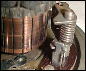
Remove the carbon brush from the third brush holder. If necessary, bend the brush holder stop towards the brush holder pin until you have a minimum of ¼” clearance between the brush holder and the copper commutator bars. The stop is a metal tab that protrudes from the end plate parallel to the armature. The brush spring attaches to one edge of the tab; the opposite edge serves as a stop to prevent the brush holder from striking the commutator if the brush becomes too short or is removed. This will provide adequate clearance between the brush holder and the commutator when the new wire connections are made here. (See Figure 1)
DO NOT PROCEED UNTIL ALL GENERATOR PROBLEMS HAVE BEEN CORRECTED!
Figure 1: Third brush holder and stop
INSTALL THE REGULATOR ASSEMBLY ON THE GENERATOR
- Attach the generator output wire to the regulator terminal marked “A” or “GEN”.
- Insert the green regulator wire into the generator through the same hole as the existing generator wire. Carefully pull the entire green wire into the generator while lowering the regulator down onto the generator.
- Attach the regulator to the generator using the original mounting hardware, including the curved spacer plates under the feet. If these plates are not used, the “A” or “GEN” terminal screw may touch the chassis and short out. Be sure there is adequate clearance between this terminal and the generator body.
- Slip the shrink tubing over the end of the green wire and strip 3/8” of insulation from the end of the wire.
- Crimp and solder the ring terminal onto the green regulator wire. Install the shrink tubing over the end of the terminal and heat it using a match or lighter to insulate and strengthen the soldered wire connection.
- Using the third brush holder as a junction terminal, connect the green regulator wire and the generator field wire together. Use the original brush mounting screw and new lock washer. The round aluminum spacer must be used in place of the third brush. NOTE: DO NOT install the third brush back onto the brush holder. Reinstallation of the third brush will disable the regulator and will limit the maximum generator output!
- Position the green regulator wire and terminal so that it will not be pinched by the generator frame or rub on the armature. Double check to be sure there is a minimum of ¼” clearance between the third brush holder and the commutator bars. Readjust the brush holder stop if necessary (See figure 1 above)
- Carefully inspect all internal generator wires to be sure they are clear of the rotating armature and are not pinched. Reposition and tie the wires up if necessary. A wire rubbing on the armature will quickly cause a short and damage the generator and or regulator. This is critical; take the time to get this right.
- Replace the generator cover strap, reinstall the generator and insure adequate ground to the generator and regulator. NOTE: A poor ground to the regulator will cause a high charge rate at all times. Poor grounding of the generator will cause other problems as well. BE SURE THAT THE REGULATOR, GENERATOR AND BATTERY ARE PROPERLY GROUNDED TO THE MOTORCYCLE CHASSIS.
- Prior to operating the generator, service the battery. Be sure that the battery is the correct size for your application. Check the fluid level and fully charge the battery. Neither the generator nor the regulator will solve underlying battery problems.
UNDERSTANDING THE GENERATOR / REGULATOR OPERATION:
The old three brush regulating system and cutout relay has now been replaced with a 2 brush generator and electronic regulating system. This new system will automatically adjust the generator output as needed in an attempt to maintain optimum battery voltage. It is normal for the regulator to get hot during operation. There are no field adjustments to be made to the regulator. Proper care of the generator bearings and brushes is still required. There are three key points to keep in mind in order to optimize the performance of the new generating system:
- Take care of the battery; Purchase a high quality lead acid, AGM, or Gel battery of the largest capacity that will fit your application. Proper maintenance is still important, even with the improved charging system. Check the fluid level regularly (if applicable) and keep all batteries on a maintenance charger when stored for long periods of time. Keep the battery terminals clean and verify proper grounding of the battery, generator and regulator to the chassis at all times.
- Manage the electrical loads on your machine. This new charging system should be capable of continuously powering all stock lighting and ignition equipment as well as providing a maintenance charge to the battery. Or, it can provide power for ignition and recharging a low battery, if given enough running time. It CANNOT charge a low battery and run all the lights plus ignition at the same time! Under ideal conditions, and depending on the model, the generator is rated to produce a maximum of approximately 12.5 amps output @ 7.0 volts. That equates to 87.5 watts of power. DO NOT EXPECT THE GENERATOR TO PROVIDE MORE POWER THAN THIS, IT CANNOT. The result will be a dead battery and possibly a damaged generator or regulator. Accurately measure or calculate the current draw of all equipment and accessories on the motorcycle. Add at least 1 amp for battery charging. Be sure this total amount does not exceed the maximum output capacity of the generator
- Understand and monitor the ammeter: The ammeter indicates if power is flowing into or out of the battery. This is important to remember and can be used as a diagnostic tool. If the ammeter shows a + charge, power is flowing into the battery from the generator. If the ammeter indicates a − charge, power is flowing out of the battery to supply some electrical demand such as lights or ignition. If the ammeter indicates a 0 charge, the system is balanced, no power is flowing into or out of the battery.
With a fully charged battery, the ammeter should read as follows:
|
Ignition / Light Switch Position |
Engine RPM |
Ammeter Indication |
|
OFF |
OFF |
0, or CENTERED |
|
IGNITION only |
OFF or LOW IDLE |
SLIGHT – CHARGE, or 0 |
|
IGNITION only |
MODERATE or HIGH |
SLIGHT + CHARGE |
|
IGNITION and LIGHTS ON |
OFF or LOW IDLE |
LARGE − CHARGE |
|
IGNITION and LIGHTS ON |
MODERATE or HIGH |
SLIGHT + CHARGE |
NOTE: If the battery is low, a higher rate of charge will be indicated when the engine is above idle. It may take quite some time to completely recharge the battery but eventually the ammeter should indicate only a slight + charge rate while running.
 Figure
2:
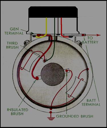
Original internal wiring diagram showing:
Figure
2:
Original internal wiring diagram showing:
· Adjustable third brush regulating system
· Cutout relay installed
· Negative ground to chassis
· Positive field control, using third brush.
· System works adequately, but performance is limited by third brush regulating system
 Figure
3:
Modified internal wiring diagram showing:
Figure
3:
Modified internal wiring diagram showing:
· Third brush has been eliminated, but brush holder acts as a junction terminal.
· Solid state voltage regulator installed on original cutout relay base with wires connected to:
RED: “BATT” or battery terminal of cutout
YELLOW: “A” or “GEN” terminal of cutout
BROWN: To the cutout relay base (as a ground)
GREEN: To the 3rd brush holder with the generator field wire
Outward appearance is not changed but performance capability is greatly enhanced
TROUBLESHOOTING GUIDE
|
Regulator not properly grounded |
||
|
Generator field wire shorted to generator + wire or brush |
||
|
Faulty regulator |
||
|
Battery severely discharged or damaged |
||
|
Excessive lighting load |
||
|
Remove third brush, see step 6 in “Prepare the Generator for installation of the of the regulator |
||