

Installation and Operating Instructions
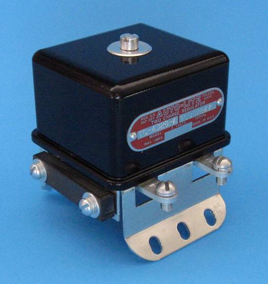
Solid State “TC” Voltage Regulator
For High Output, 6 Volt, Autolite GDE Model Generators
“Now you can turn your lights on anytime!”
APPLICATION: This solid state voltage regulator is designed specifically to fit high output three brush GDE model Autolite generators equipped with 6 volt TC model regulators. This was standard equipment on Indian motorcycles from 1948 through 1953 and optional equipment from 1938-1947.
PROPER INSTALLATION WILL REQUIRE THE FOLLOWING:
A properly functioning 6 volt Autolite model GDE generator configured for Negative Ground Operation Only
Elimination of the third brush inside the generator, converting it to a two brush system.
OVERVIEW OF OPERATION: Installation will eliminate the often troublesome three brush regulating system, mechanical regulator and cutout relay. It will be replaced with a solid state current and voltage regulator mounted inside the aluminum housing. Installed properly, this regulator will allow complete and accurate current and voltage regulation of the generator. Maximum output voltage will be limited to approximately 7.25 volts. Current output will range from approximately .75 amps, up to the maximum allowed by the generator, approximately 20 amps, depending on demand and battery size.
SPECIFICATIONS:
* 6 volts DC nominal, 7.25 volts maximum output
* 20 amps continuous, 25 amps maximum, intermittent
* Negative system ground
* Negative field winding control
PREPARE THE GENERATOR FOR INSTALLATION OF THE REGULATOR:
Be sure the generator is working properly before installing the regulator. This may require removal of the generator from the motorcycle. Perform any necessary maintenance to the bearings, brushes, wiring, armature and field windings before proceeding. This is a good time to have a generator shop perform a load test on your generator.
If the generator is in good working condition, removal and inspection may not be necessary. Installation of the regulator may be performed with the generator installed on the motorcycle.
To avoid damage to the generator, regulator, or wiring, DISCONNECT THE BATTERY FROM THE MOTORCYCLE BEFORE PROCEEDING. Service and charge the battery while completing the installation.
Carefully mark and remove all wires connected to the regulator. Remove the original regulator from the generator.
Remove the generator inspection cover strap, exposing the brushes and internal wiring.
Remove the field “+” wire connected to the third or “adjustable” brush. Connect it to the generator “+” brush terminal along with the generator output wire (previously connected to the A terminal of the regulator). Reposition and tie the wires up as needed. A wire rubbing on the armature will cause a short and damage the generator or regulator.
Remove the carbon brush and screw from the adjustable third brush holder. If necessary, bend the brush holder stop towards the brush holder pin until you have a minimum of ¼” clearance between the brush holder and the copper commutator bars of the armature (See figure at right). WARNING: FAILURE TO PROVIDE ADEQUATE CLEARANCE WILL DAMAGE THE COPPER COMMUTATOR BARS ON THE GENERATOR ARMATURE. An alternative would be to disassemble the generator and remove the third brush holder assembly entirely, as it is no longer needed.
If the generator was disassembled for any reason, the field windings must be re-polarized. This may be done by motorizing the generator, which can also serve as a basic test of generator operation. Proceed as follows:
Remove the generator drive belt if still attached.
Use a fully charged 6 volt battery with suitable jumper wires and connect it to the generator as follows;
Battery “-” terminal to the generator chassis.
Battery “-” terminal to the external generator field wire (previously connected to the “F” terminal of the regulator)
Battery “+” terminal to the generator output wire (previously connected to the regulator “A” terminal).
At this point the generator should turn smoothly in the direction of rotation for the appropriate application. It may be necessary to turn the generator by hand to get it started.
If the generator does not turn smoothly in the correct direction, or if there is any reason to suspect generator problems, installing a regulator at this point will not fix a poorly operating generator!
DO NOT PROCEED UNTIL ALL GENERATOR PROBLEMS HAVE BEEN CORRECTED!
INSTALL THE NEW REGULATOR ASSEMBLY ON THE GENERATOR
Re-install the generator inspection cover strap, carefully routing the two wires through the hole.
Attach the generator output wire (from the “+” brush of the generator) to the regulator terminal marked “A” on the underside of the regulator.
Attach the generator negative field wire to the terminal marked “F” on the underside of the regulator.
IMPORTANT NOTE: DO NOT INSTALL A FUSE IN THE REGULATOR FUSE HOLDER AT ANY TIME!
Attach the regulator to the generator inspection strap using the original mounting hardware.
Consider having the generator/regulator combination load tested at a reputable generator shop before proceeding. This is an accurate indicator of maximum output capacity and is helpful when determining the allowable lighting loads.
Attach the battery wire to the external terminal marked “B” on the regulator.
Attach the indicator light wire (if equipped) to the external terminal marked “T” on the regulator.
BE SURE THAT THE REGULATOR, GENERATOR AND BATTERY ARE PROPERLY GROUNDED TO THE MOTORCYCLE CHASSIS AT ALL TIMES. ALL WIRE CONNECTIONS MUST BE CLEAN AND TIGHT. A poor ground to the regulator or generator will prevent the generator from charging at all and may damage the regulator. Consider the addition of a dedicated ground wire from the generator chassis to the battery (-) terminal.
Prior to operating the generator, service the battery. Check the fluid level and fully charge the battery.
UNDERSTANDING THE GENERATOR / REGULATOR OPERATION:
This new regulating system will automatically adjust the generator current output as needed in order to maintain optimum battery voltage. It is normal for the regulator to get hot during operation. There are no field adjustments to be made to the regulator or generator. Proper periodic maintenance of the generator bearings and brushes is still required.
There are four key points to keep in mind in order to optimize the performance of the new generating system:
Understand the limitations of the generator. Installation of this regulator does not enable the generator to produce any more power than it was originally designed to produce. The voltage regulator will only adjust the charging rate of the generator up or down, within the performance range of the generator.
Proper battery maintenance is required! Purchase a high quality lead acid, AGM, or Gel battery of the largest capacity that will fit in your application. Proper maintenance is still important, even with the improved charging system. Check the fluid level regularly (if applicable) and keep all batteries on a maintenance charger when stored for long periods of time. Keep the battery terminals and wire connections clean and tight. Verify proper grounding of the battery, generator and regulator to the chassis at all times. Remember, the generator CANNOT charge a seriously low battery and run all the electrical equipment at the same time.
Manage the electrical loads on your machine. With the generator and battery in good condition, this new charging system should be capable of continuously powering all stock lighting and ignition equipment as well as providing a maintenance charge to the battery. Accurately measure or calculate the current draw of all equipment and accessories on the motorcycle. Add at least 1 amp for battery charging. Be sure this total amount does not exceed the maximum output capacity of the generator. Remove the generator and have it load tested if needed. DO NOT expect to run non-standard lights or additional accessories with a stock generator. The result may be a dead battery!
Understand and monitor the ammeter (or dash light): The ammeter indicates if power is flowing into or out of the battery. If the ammeter shows a + charge, power is flowing into the battery from the generator. If the ammeter indicates a − charge, power is flowing out of the battery to supply some electrical demand such as lights or ignition. If the ammeter indicates a “0” charge, the system is balanced, no significant power is flowing into or out of the battery. The function of the dash light (if so equipped) is to warn the operator when generator output voltage has dropped below battery voltage, an indication that the generator is not charging at all.
CHECK THE OPERATION OF THE GENERATOR / REGULATOR:
Attach a volt meter to the battery terminals. If fully charged, it should read approximately 6.6 volts, or more.
Start the motorcycle and leave all lights off. Observe the ammeter / dash light for proper charge. See the table on page 4 for details. It may be necessary to increase the engine RPM a bit to turn the regulator on (each time the engine is started). Once on, the regulator will continue to maximize generator output even at very low RPM.
Observe the volt meter attached to the battery. It should read approximately 7.25 volts.
Turn on the lights, increase engine RPM to a moderate cruising speed and observe the ammeter / dash light for indication of positive charge. Battery voltage should remain near the 7.0 to 7.25 volt range.
Return engine to idle speed. Note ammeter indicating discharge. Battery voltage will be decreasing.
Turn off lights and observe ammeter for slight charge, or indicator light off and battery voltage steady, or increasing.
Turn off engine. Observe “0” ammeter reading or indicator light off. Battery voltage should stabilize near 6.6 volts.
With a fully charged battery, the ammeter (or dash light) should read as follows:
Ignition / Light Switch Position
Engine RPM
Ammeter Indication OR:
Dash Light
OFF
OFF
0, or CENTERED
OFF
IGNITION only
OFF
SLIGHT – CHARGE
ON
IGNITION only
LOW IDLE
0 or SLIGHT + CHARGE
OFF
IGNITION only
MODERATE or HIGH
SLIGHT + CHARGE
OFF
IGNITION and LIGHTS ON
LOW IDLE
LARGE − CHARGE
OFF
IGNITION and LIGHTS ON
MODERATE or HIGH
SLIGHT + CHARGE
OFF
NOTE: If the battery is low, a high rate of charge will be indicated when the engine is above idle. It may take quite some time to completely recharge the battery but eventually the ammeter should indicate only a slight “+” charge rate while running.
TROUBLESHOOTING GUIDE
Generator field wire shorted to ground
Faulty regulator
Battery severely discharged or damaged
Excessive lighting load
Remove third brush, see steps 6 and 7 in “Prepare the generator for installation of the regulator on page 2.