Splitdorf Generator
Overview
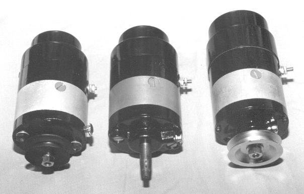
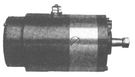
Left to Right
DU-1, DU-5H, DU-7
The DU series of generators began production in late 1917 or early 1918. This was an outgrowth of the Mag-Dynamo previously available as an option on many motorcycles of the period. It was a compact and efficient unit designed specifically for motorcycle use. Much speculation exists (at least in my mind!) on the origin of the "DU" designation used on this series. My best educated guess is that it stands for "Dynamo Unit #1". The basic design of the DU-1 proved sound and reliable. Throughout a succession of improvements all the way up to DU-7, the basic design remained unchanged.
Basic features of all DU model generators
DUs are typical of automotive generators of the period. It is a 3 brush, shunt wound, self regulating design. This means that as generator rpm increases so does amperage - up to a point. A phenomena known as armature reaction causes generator output to decrease above a certain speed. The armature has 22 coil windings and 11 commutator segments. Thrust type ball bearings are used at both ends. Field coils are series wound and made of approximately 240 turns of .025" copper magnet wire. The body or frame is made of 3.25 OD steel tubing. The commutator head is a 3 legged casting which serves the dual purpose of mounting the commutator plate with brush holders on the inside and the cutout assembly on the outside. The cutout is designed to fit under the dust cap on the commutator head.
Specific features of the DU-1
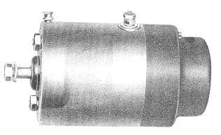
The DU-1 armature has a 3/8" diameter pulley and commutator end shaft. It uses a pulley or chain sprocket with a straight hole, retained with a woodruff key. The commutator head is made of cast iron and is attached by two ¼" studs that run through the length of the body to the drive head. Special nuts are used to retain the drive head on the studs. Critical to the proper operation of the generator is the positioning of the commutator head relative to the field coils. Because of this, different commutator heads are used for clockwise and counter-clockwise rotation. The position of the ¼" stud holes is unique to each. A small flip top Gits oiler is mounted on the outside of the body at the pulley end. A small trough is riveted to this inside of the drive head. This trough carries oil from the Gits oiler to the drive end bearing. Bearings are 1.00" OD x .375" ID. A mechanical cutout driven by the armature is mounted on the commutator head. Maximum current output is rated at 4.5 amps at 2500 generator rpm.
Specific features of the DU-3
This is a very unusual model. I have only seen a couple of them; one of which is now in my collection. The only application I know of for this generator is the 1922 Cleveland single. It may have been used in '23 and '24 as well but I've not been able to confirm this. If anyone has literature showing its application I'd sure like to hear from you. The DU-3 is very similar to the DU-5 described below with one notable exception â the cutout. The cutout is a very complicated electrical device fitted to the commutator head. It is much larger than any other cutout used including that of the DU-7. Unlike every other Splitdorf generator, the DU-3âs end cover is straight sided. In other words there is no step-down in size at all. The other unique aspect of this model, if the Splitdorf literature is to be believed is the rotation speed. Original Splitdorf literature states that maximum voltage is regulated to 6.5 volts at 6000 armature rpm; more than double the maximum speed of the DU-1 or DU-5. In my opinion, this is hard to believe. In the future I plan to service my DU-3 and put it on the test stand for evaluation. I will add my findings to this page when I do.
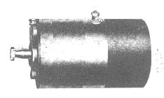
Specific features of the DU-5
In May of 1920 Splitdorf announced that the new DU-5 was superseding the DU-1. I don't believe this means that all motorcycle manufactures immediately changed to the DU-5. No doubt many DU-1s were still in stock and they were surely used up first. So what makes a DU-5 different? Several improvements were incorporated to make it more durable and reliable. The drive end shaft was increased in size from 3/8" to 13 mm (.512") to reduce the chance of a bent shaft from too tight a belt or chain. The pulley (or sprocket) now used a 12 degree tapered hole for improved alignment. Bearings on both ends were changed to standard metric sizes. The Gits oiler was moved to a more protected position on the bearing boss instead of on the body. A single armature was used for either rotation instead of a unique one for each. In order to economize on production the commutator head was made with two sets (4 total) of ¼" mounting holes to allow the same part to be used for either rotation. Long slotted machine screws retain the drive head instead of the previously used studs and special nuts. The same mechanical cutout was used until mid 1925 when a new electrical cutout, the A-10 became available.
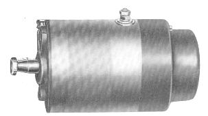
Specific features of the DU-7
The DU-7 was developed in late 1927 and appeared in early 1928. It was a significant improvement over the DU-5 for several reasons. The cast iron commutator head of the previous models was prone to breakage under rough service. Consequently, an aluminum head was developed which was lighter and purportedly more durable. However my experience has shown just as many broken DU-7 commutator heads as DU-1s and DU-5s. With the end cover removed the aluminum head is easily identified. A 3 amp fuse was incorporated into the field coil circuit to protect the coils from excessive current. Maximum output was increased to 5 1/2 amps at 3500 rpm. A larger, improved electrical cutout was developed to handle the higher current. The cutout cover bulge was correspondingly enlarged to 2-15/16".